POWER SYSTEMS – KNOWLEDGE VACUUM IN SRILANKA
Posted on April 9th, 2016
By Kanthar Balanathan
DipEE (UK), GradCert (Rel Eng.-Monash), DipBus&Admin (Finance-Massey), CEng. MIEE, MIE (Aust), CPEng (Ret)
Former Director and Specialist Power Systems Engineer (Australia)
In the month of March 2016, two transformer explosions struck at Biyagama and Kotugoda CEB Grid sub-stations. Media reports state that the German specialists, after investigations revealed the explosion was in the diverter switch, which is the On Load Tap Changer (OLTC). The load throw off (LTO) of the capacity of this Biyagama transformer also cause stability issues and tripped the generators at the Lakvijaya (Norocholai, Puttalam) power plant. Capacity of the generators at Lakvijaya Power Station (LPS) is 3 x 300MW. Transformer at Biyagama is rated for 220/132/33kV. Media information state that feeder lines tripped after the transformer caught fire at Biyagama.
A report by Maheesha Mudugamuwa in the island state that the power station trip was caused by a lightning strike. http://www.island.lk/index.php?page_cat=article-details&page=article-details&code_title=141040.
This statement cannot be true. May be the first incident of trip. During the period when this disaster occurred at about 2.15 p.m. there was no lightning or rain. The environment too was normal. Indeed, there was no rain at all in the region. Ref: http://lankaenews.com/news/1203/en
Another transformer explosion at Kotugoda caught fire similar to the explosion at the Biyagama Grid Sub-station. Both transformers are similar single phase auto-transformers. It could be a Type Fault” on these type of transformers. Type: Takaoka Autotransformer (1983) 132//33kV (secondary), 200/3, 250/3, 60/3 MVA, YNa0d1, ONAN/ONAF with 13 taps on both. There are three of this type one on each of the phase. Are these transformers made in Germany or Japan?
- Possible cause: Diverter switch may have contained excessive amount of combustible gases.
- The contacts of the tap changer may have been pitted causing generation of sparks while moving from one tap to the other.
- Oil may have had exceeded levels of moisture.
- Oil condition may have been as sludge, brown oil.
- May be a Type Fault”.
- What about the Buchholz relay in the diverter switch. Did it operate to trip?
- What about the Buchholz relay for the Transformer? Did it operate?
- Analysis should be carried out on identifying what relays tripped.
Root cause of failure therefore, has to be generation of sparks in the diverter switch, subject to excessive level of combustible gases. Primary cause of failure is nothing other than, lack of condition monitoring, and maintenance practice. Speculating about sabotage in the media, is an irresponsible statement, and kind of pass the monkey in a way.
Tripping of feeders:
It was observed from photographs, smokes were released in high volumes, due to the explosion.
It is possible that the smoke clouds, if concentrated under the power lines could ionise and trip on earth fault. Reason being dielectric breakdown of the air as a result of Carbon soots/ionisation. This could be verified from the operated relays. If E/F relays has operated on lines then it should be investigated. (Take note, the air was dry and no rainfall at the time of line trip)
- The author of this paper has experience on 132kV lines trip due to lack of wayleaves clearance, and bush fire.
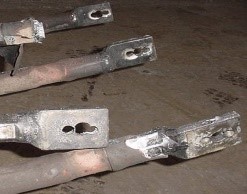
- [An example of an explosion of the 6.6 kV terminal box of a 20 MVA transformer.
 |
 |
 |
The bolt holes of the lug is self-explanatory. The engineer who approved the connection had not thought of the risk of the connection. This was prior to me joining the 6 x 280 MW thermal station. The terminals were tightened without locknuts. When 6.6 kV, 900 HP Pulveriser SC motor was started, this explosion ripped open the terminal cover, cut the oil line and caught fire. Cause: The terminals have become loose, and the starting current of the motor caused the cables to move and initiate sparks, ionise the chamber, flashover, and explode (L-E, L-L, 3 phase short). Root cause of failure: Improper lug connection becoming loose with time. The survey cycle was placed at 6 years for major and 3 years for minor. Transformer survived but had to replace the cables. Relays tripped: E/F, Diff, O/C. Author carried out the investigation and the committee accepted the analysis and conclusion.]
- g. a 275 MVA transformer failed and caught fire as a result of partial discharges in the EHV bushings and was on fire for 3 days in New Zealand.
- A 400 kV transformer on fire at ESKOM

Chief Engineer of Biyagama Grid sub had already requested action sometimes back. Quote: The Chief Engineer, who was in charge of the transformer at the Biyagama Sub-Station, has reportedly informed the Ceylon Electricity Board (CEB) several times that it needed to be repaired, but no steps had been taken to heed his advice. It is also learnt that the government has decided to hold an inquiry into why the General Manager of the CEB had not taken any action regarding the transformer, though he was informed about the need to do so”. Ref: http://lankalightnews.blogspot.com.au/2016/03/biyagama-ce-warned-ceb-often.html
It is beyond doubt that the transformers were beyond operable condition, and non-electrical people should refrain from making statements about the failures. The Chief Engineer is in a better position to give accounts of the failure and the pre-failure condition of the transformers.
This sought of act is not new to SriLanka: The boss is always right, and engineers and managers at every level are controlled by the politicians, who do not understand the difference between DC and AC. The Public Relations Officer, (PRO), if one available at the CEB, should release information on failure, subject to approval by the CEB management. The Chairman of CEB, Mr. Anura Wijepala, is a qualified competent electrical engineer, and it is sure that his hands may have been tight, controlled by the politicians and non-technical administrators.
There may be several transformers which may not have been condition monitored and maintained. Condition of the oil should be checked every 6 to 12 months. Colour and flashover voltage.
- Diverter switch has to be checked and maintained regularly. Survey cycle should be fixed.
- Contacts get pitted due to frequent operation. Pitted contacts have to be replaced.
- Gas evolution such as Methane, Carbon Monoxide etc.
- DGA analysis should be carried out yearly.
- It is possible that the pitted contacts would have generated sparks in the diverter switch, and the contents of combustibe gases would have ignited, thus creating the explosion OR
- Winding failure due to cellulose Degree of Polymerisation (DP) becoming too low.
However, as the German engineers have concluded that the failure was due to diverter switch failure, the author assumes that the diverter switch have become beyond operable condition. It is possible to check in the SCADA whether the OLTC operated at the time of the explosion. I.e. change taps.
Standards and Limits
IEC 60599:1999 stipulates the following values for sealed Instrument transformers.
| H2 | CO | CO2 | CH4 | C2H6 | C2H4 | C2H2 |
| 300 | 300 | 900 | 30 | 50 | 10 | 2 |
IEC 60599:1999 suggests the following causes for various levels of energy.
| Fault | Examples |
| Partial discharges | Incomplete impregnation results in discharges in cavities plus high humidity in paper, oil super saturation or cavitation. |
| Discharges of low energy | Sparking or arcing between bad connections, or shielding rings, adjacent disks or conductors of winding, broken brazing. |
| Discharges of high energy | Flashover, tracking or arcing of high energy or with power follow-through |
| Thermal fault <300C | Overloading of transformers, restriction of oil flow |
| Thermal fault 300C< t <700C | Defective contacts between bolted connections, connections from cable and draw rod of bushings |
| Thermal fault > 700C | Large circulating currents in tank and core, Minor currents in tank walls created by high uncompensated magnetic field, shorting links in core laminations |
Determination of Breakdown Voltage
AS1767.2.11999 States the following method for determining the break down voltage:
Apply voltage to the electrodes and uniformly increase voltage from zero at the rate of 2.0 kV S-1 ±0.2 kV S-1 until breakdown occurs. The breakdown voltage is the maximum voltage reached at the time the circuit is opened either automatically or manually. Carry out six breakdowns on the same cell filling allowing a pause of at least 2 minutes after each breakdown before re-application of voltage. Check that no gas bubbles are present within the electrode gap”
A breakdown voltage of 30 kV (gap of 2.5mm, ±0.05mm) may be acceptable and normal value of Shell Diala M is >70kV.
Lakvijaya (Norocholai) Power Station
The power station has 3 x 300MW turbo-alternator units driven by steam turbine and fuelled by pulverised coal.
The generators should have been tested for 50%-100% Load Throw Off at the time of commissioning. Generally a resistor bank of 50 MW is installed at the step up station to be used for load throw checks. May be this was not tested.
Power System Stabiliser
Power systems stabiliser (PSS) is a control system that is installed with the AVR to improve stability of the generators. PSS is a supplementary excitation controller used to damp generator electro-mechanical oscillations in order to protect the shaft line and stabilise the grid.
The basic types of tests usually performed. Ref: http://www.geenergyconsulting.com/practice-area/global-power-projects/power-system-stabilizers
- Step test in AVR reference (base load – without PSS).
2. Gain margin test to determine the PSS gain to be used.
3. Step test in AVR reference (base load – with PSS).
Optional additional testing for new design units or per customer requirements are:
- AVR uncompensated transfer function.
2. PSS transfer function
Present day thermal units have digital AVR + PSS installed on large units to improve power systems stability.
About the author:
The author joined the then DGEU in December 1965 as a Foreman Apprentice, and on completion was posted to Inginiyagala power station as a shift officer. Resigned in Sept. 1967 and proceeded to UK to further studies, and returned with a job to work for Ceylon Cement at KKS, and rose to Works Engineer (Elect). Left SL in Feb 1977 and since then has worked on sub-transmission line construction and has over 30 years’ experience in large turbogenerators, GT, CC plant, and heavy electrical equipment. Have worked in UK, Nigeria, Zimbabwe, NZ and Australia. Could reach on email: pengsol@bigpond.net.au. Retired after a position of Director/Specialist Power Systems Engineer with Power Engineering Solutions Pty Ltd. Currently a freelance journalist.
April 10th, 2016 at 2:04 am
Kanthar,
Many thanks for illuminating the possible defects in the Electrical Power Systems in Sri Lanka.
There is another side which is the Lak Wijaya – Norocholai Coal Power Plant. From what I have read so far it is not clear whether there are competent mechanical engineering personnel in this installation capable of running and operating coal powered high pressure boiler installations? Apparently the power plant does not have sufficient back up uninterrupted power supply – usually banks of diesel generators which kicks into operation automatically once there is power failure) to operate the boiler auxiliaries – cooling pumps etc (apparently requiring 30 MW of power) at the time of a power failure to keep the boiler – ‘banked” so that it can be brought back into operation soon after the electrical systems are repaired and ready.
My reading of the problem seems that Sri Lanka purchased – one off Coal Powered Power Plant from China, got them to install it and thought everything would be hunky dory! CEB should have understood the nature of the problem when they integrated a 900 MW plant into the existing grid. In China if one Power Plant breaks down there are enough back up power from other in the grid to keep the auxiliaries running. This is not the case in Sri Lanka. Perhaps to cut down costs they opted out, not to include the back up UPS.
I also hear that the CEB is run by mainly electrical engineers and mechanical engineers have no say in making important decisions.
It seems to me that it is best that Lak WIjaya Power Plant be run independently by competent personnel not under the ‘thumb’ of the CEB Electrical Engineers. They can generate power and sell it to the CEB. To my mind a Coal Powered Power Plant is almost 80% mechanical installation, main electrical discipline coming after the steam turbine. Operating a pulverised coal powered plant is extremely dicey – you should know having been in Ceylon Cement in KKS.
I am a layman in these matters and perhaps you can illumine the situation better.
April 11th, 2016 at 5:12 am
As a qualified power as well as an electronic engineer(London),I full agree with you. Please contribute more. They seem to run that industry in an a haphazard way. Not anything like the way my late dad operated the DGEU during the colonial time. For a simple diversion or changeover they simply switch off sevral houses, instead of working with a live set up.In London these operations are done daily and not once they have switched off the supply, because the factors like the back EMF throws a surge and burn the coils in equipment’s like the fridges which has inductive load. They are ignoring the power factor of the inductive loads were PF correcting condensers should be used, that will save much transmitted power.
I had a hell of a time correcting the substandard concreating the dam in Kandy and I was only 17 years old where the local AMICC guy never walked out of his of his desk and the only one that stood by me was the boss a Danish Engineer. But we still talk about a fictitious 3000 years culture and civilization. You only know how stupid we are, when you mingle with them(colonial type), work with them and above all eat and drink in the SAME TABLE WITH THEM ON EQUAL TERMS.
April 13th, 2016 at 10:51 am
Kanthar,
Thanks for writing this informative analysis.
Nimal,
“But we still talk about a fictitious 3000 years culture and civilization”
This is a wrong statement. Please go to A’Pura, Polonnaruwa, Sigiriya and open your eyes to see. If not for that civilisation and culture you will not be talking in equal terms with the Suddhas but will be a refugee like an Afgan or a Pakistani and will not be taken seriously. Agriculture sustained mainly from Rajarata is our mainstay. Every thing else is dependent on it. When we sit on the same table and eat they have asked me why you are not like one of them ( meaning some table manners). I did not say that it is due to our cultural heritage. But they know. However be careful they will watch out for your weaknesses to finish you one day. That is how they still effectively rule the world even today.
April 13th, 2016 at 1:41 pm
Nimal,
“fictitious culture” ?
Suddas taught us all the bad habits but learned from our excellent 3000 year old culture based on 5 precepts to develop their culture and civilisation which was based on genocide.
But I agree we have to wake up.
April 13th, 2016 at 1:46 pm
Nimal,
Our huge Dagobas are bigger than pyramids. Our ancient irrigation systems are still state of the art. Did you think how they constructed those ? Let me copy from the web
Yoda Ela – An Ancient Engineering Marvel
Ancient Sri Lankans are celebrated for their indigenous knowledge in irrigation. Irrigation systems of ancient Sri Lanka consist of a large number of village tanks, gigantic reservoirs and an intrinsic network of water canals connecting these tanks while supplying water to farming land.
Despite the abundance of irrigation constructions in Sri Lanka, Yoda Ela or Jaya Ganga, an 87 km long water canal carrying excess water from Kala Wewa in Polonnaruwa to ThissaWewa in Anuradhapura, is a construction dependent on remarkable instrumentation precision.Its gradient of10 to 20 cm per kilometre still baffles experts today for its minute precision.
Built during the regime of King Dathusena in fifth century AD, who also sponsored the construction of Kala Wawa reservoir, Yoda ela was constructed to convey excess water from Kala Wawa in Polonnaruwa to Thissa Wawa reservoir in Anuradhapura.
However the ancient engineering methods in calculating the exact elevation of the Kala Wewa against ThissaWawa and the exact gradient of the canal to such fine precision had been lost with the fall of the civilisation.
Moreover the ingenuity of ancient engineers is also exhibited in how Yoda Ela was designed as an elongated reservoir, which passes through traps creating sixty six mini-catchments as it flows from Kala Wawa to Thissa Wawa. The canal was not designed for the quick conveying of water from Kala Wawa to Thissa Wawa but to create mass of water between the two reservoirs, which would in turn provided for agriculture and the use of humans and animals.
Another unique feature of the Yoda Ela is that the canal has only one bund to manage the canal pressure with the influx of water. Two bunds would have increased the pressure causing damage while with one bund the water spreads on the upper side and releases the pressure creating no danger to the bund. Built along the contours the canal collects and dispenses water throughout its 87 km flow length.
Many a features had been added to the canal since its construction. King Parakramabahu who governed the country nearly 700 years after the Yoda Wawa, reconstructed the canal added more feeders to the canal starting from thirty four reservoirs found between Kala Wawa and Thissa Wawa, re-naming it Jaya Ganga or the river of victory.
The extra water from these tanks would be fed to the canal which would distribute it in an area of 180 square miles feeding 11,400 acres of paddy lands and 120 small tanks.
However part of this ingenious creation was destroyed during the attempts to create a second Jaya Ganga under the Mahaweli Development Project causing dearth of water to some parts of the dry zone while measures are now been taken to reverse the damage done to an engineering marvel of ancient Sri Lanka.